Selecting/Installing Gate Drive Resistors on the -66848 and - 66849 Modules
Low-Side Gate Drive Module PD1000-66848 and High-Side Module PD1000-66849 do not have gate resistors pre-installed. This allows you to install gate resistors of any value necessary for the tests you are performing. You must solder appropriate resistors onto both modules.
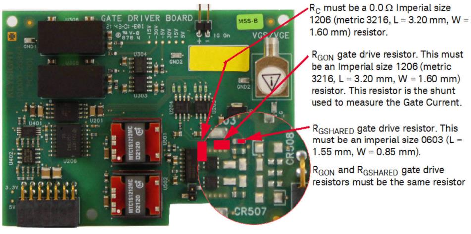
The actual Gate Drive Resistors are SMD resistors. Depending whether you choose to use a single-path gate drive or a split-path determines the actual resistor values and configuration. Figures below show the resistor arrangement for a Single-Path application and for a Split-Path Configuration.
Resistors are either an Imperial size 1206 (metric 3216, L = 3.20 mm, W = 1.60 mm) and is used in measuring the gate drive current. or imperial size 0603 (metric 1608, L = 1.60 mm, W = 0.80 mm). The 0603 resistor is smaller self destructs earlier in case of over current to protect the oscilloscope and probe.
Use identical resistors on the Low-Side and High-Side Gate Drive modules.
Installing Common-Path Gate Drive Resistors
Installing Split-Path Gate Drive Resistors

Installing Common-Path Gate Drive Resistors
Three SMD resistors must be installed on the module to create a Common-Path module.
Installing Split-Path Gate Drive Resistors
Three SMD resistors must be installed on the module to create a Split-Path module.

How to Test the Gate Drive Resistor to Ensure Proper Installation
With a DMM, measure the values of the Gate resistors.